Switch out to USB-C!
 MaxWofford
Upgrade to USB-C
Want to see the finished blueprint? Find it here
If you haven't built a schematic yet, do so in part 1. This workshop will start out by modifying the existing schematic.
First off, what is USB-C? What's USB-A?
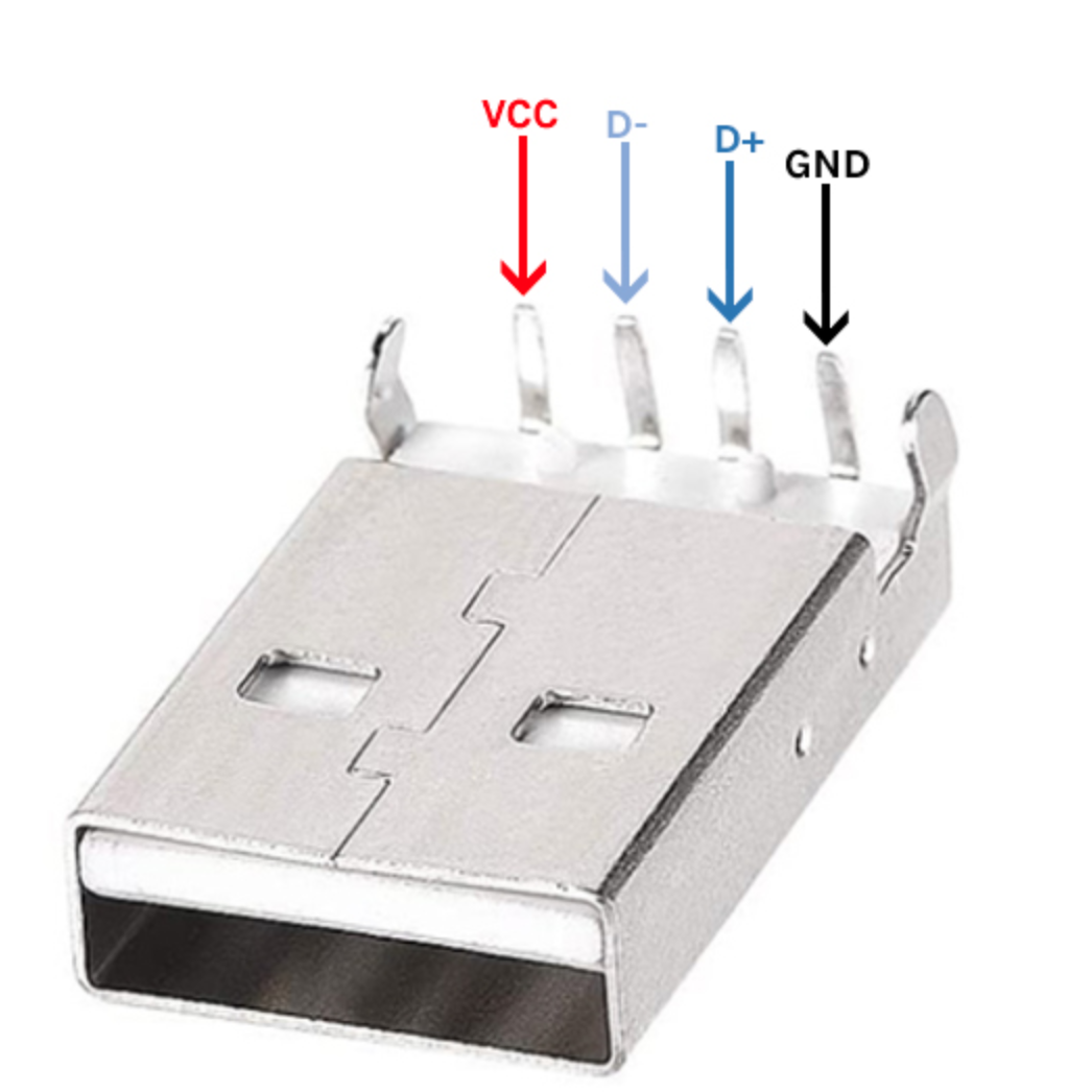
USB-A is the classic old USB port. Ever plug in a USB only to realize it's upside-down, then after flipping it it's still upside-down somehow? That's USB-A. It's what we used in the previous jam and the pinout is nice and straight forward.
USB-C is a newer type of USB that's come out since then. It's still compatible with USB-A ports, but it's reversable so it's never upside-down.
The pins on a USB-C are a little bit more complicated, but it's worth the effort to not have to flip it around.

Out with the old, and in with the new!
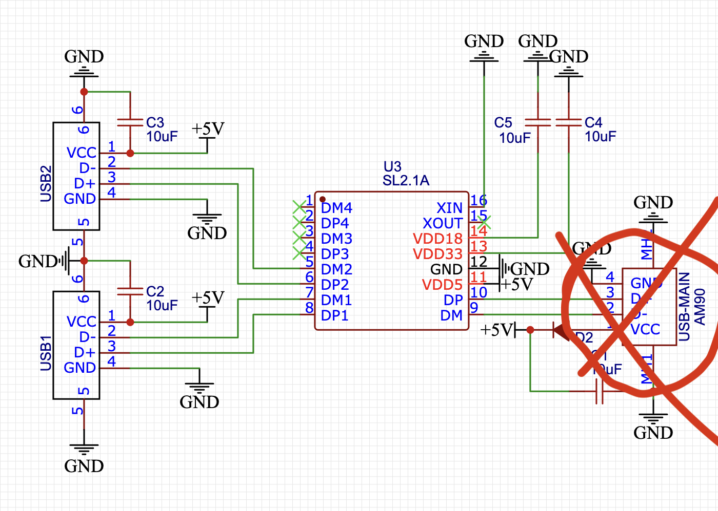
The first step is to get rid of our old work! See that USB-A port from the previous jam? Get rid of it! Just move the diode and capacitor off to the side-- we'll bring them back into the picture later.
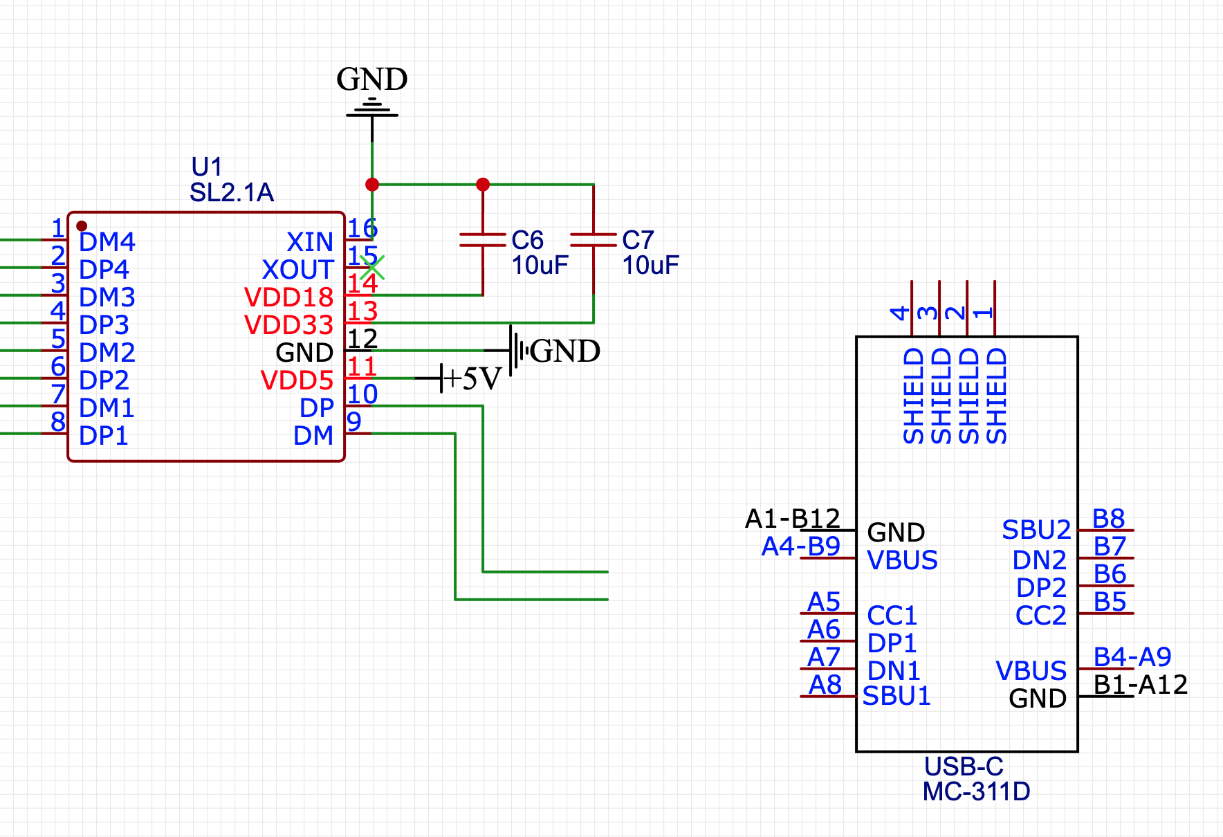
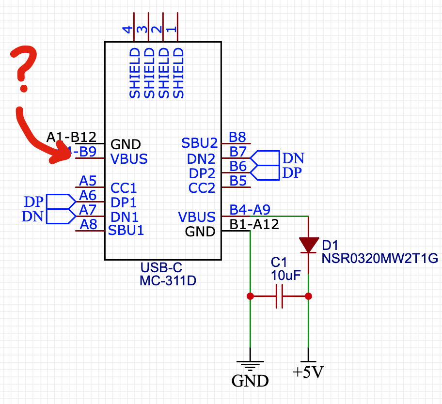
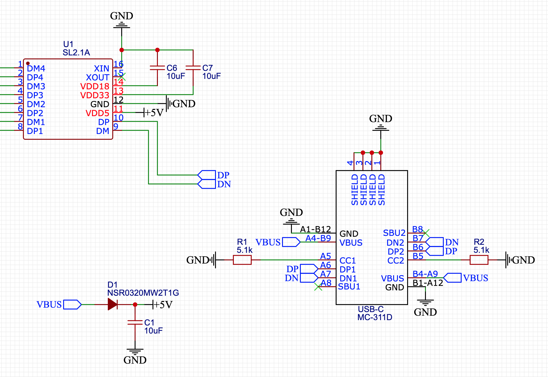
I searched LCSC for "USB-C female" and found the MC-311D. Let's drop it in!
Double the pins!
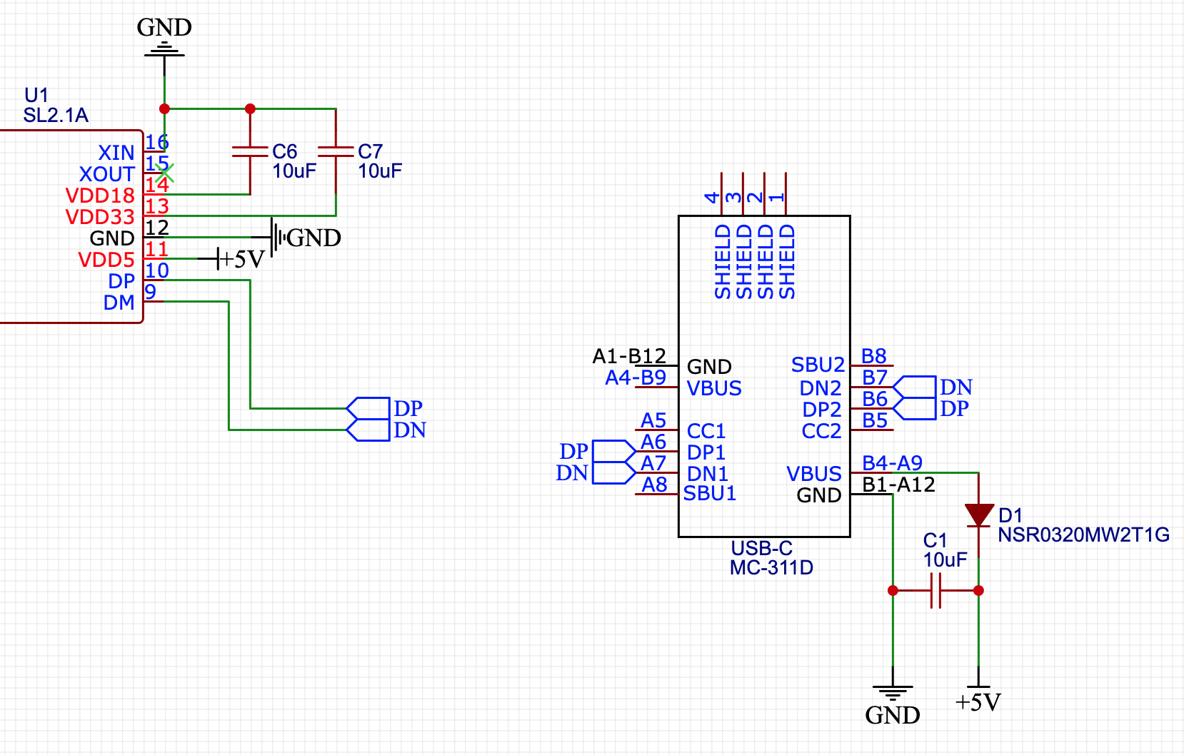
Let's wire up D+ just like we did last time...
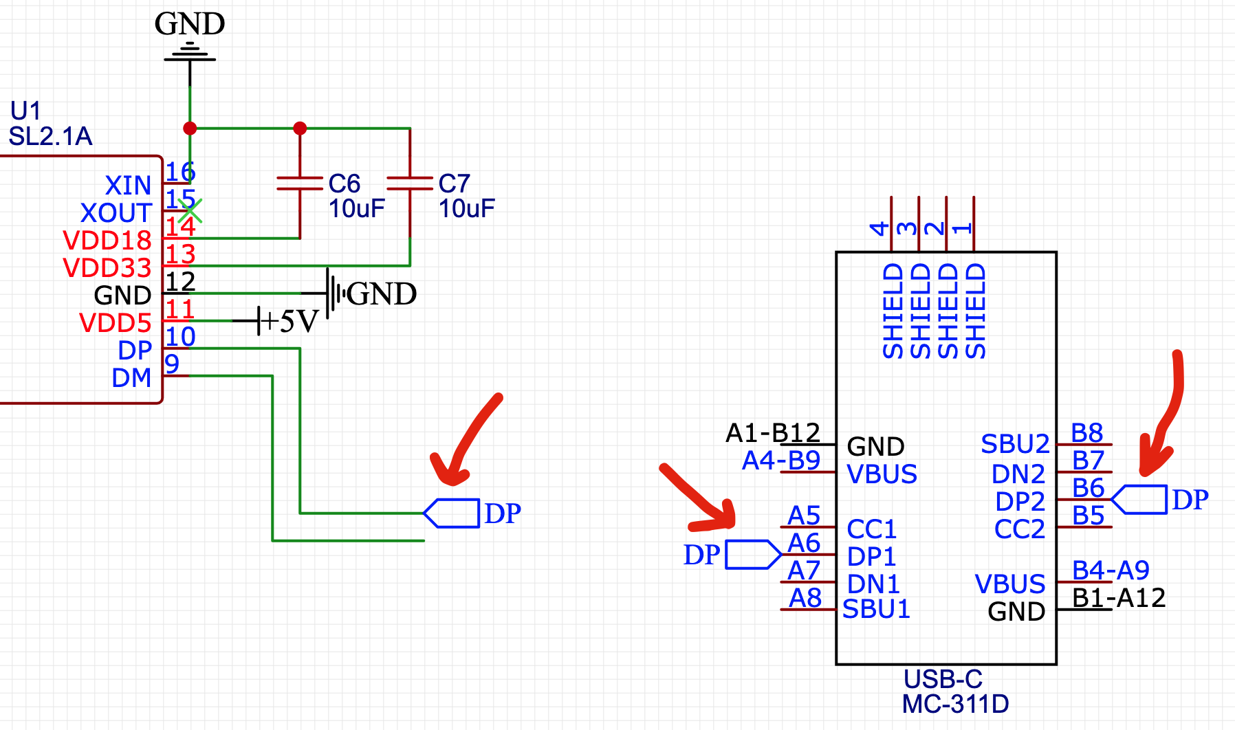
But wait, what's this?! 2 D+ pins on the USB-C port?
That's how we make it reversable! One side is for when it's plugged in one way, and the other side is for when it's plugged in the other way.
Bring back the old ports!
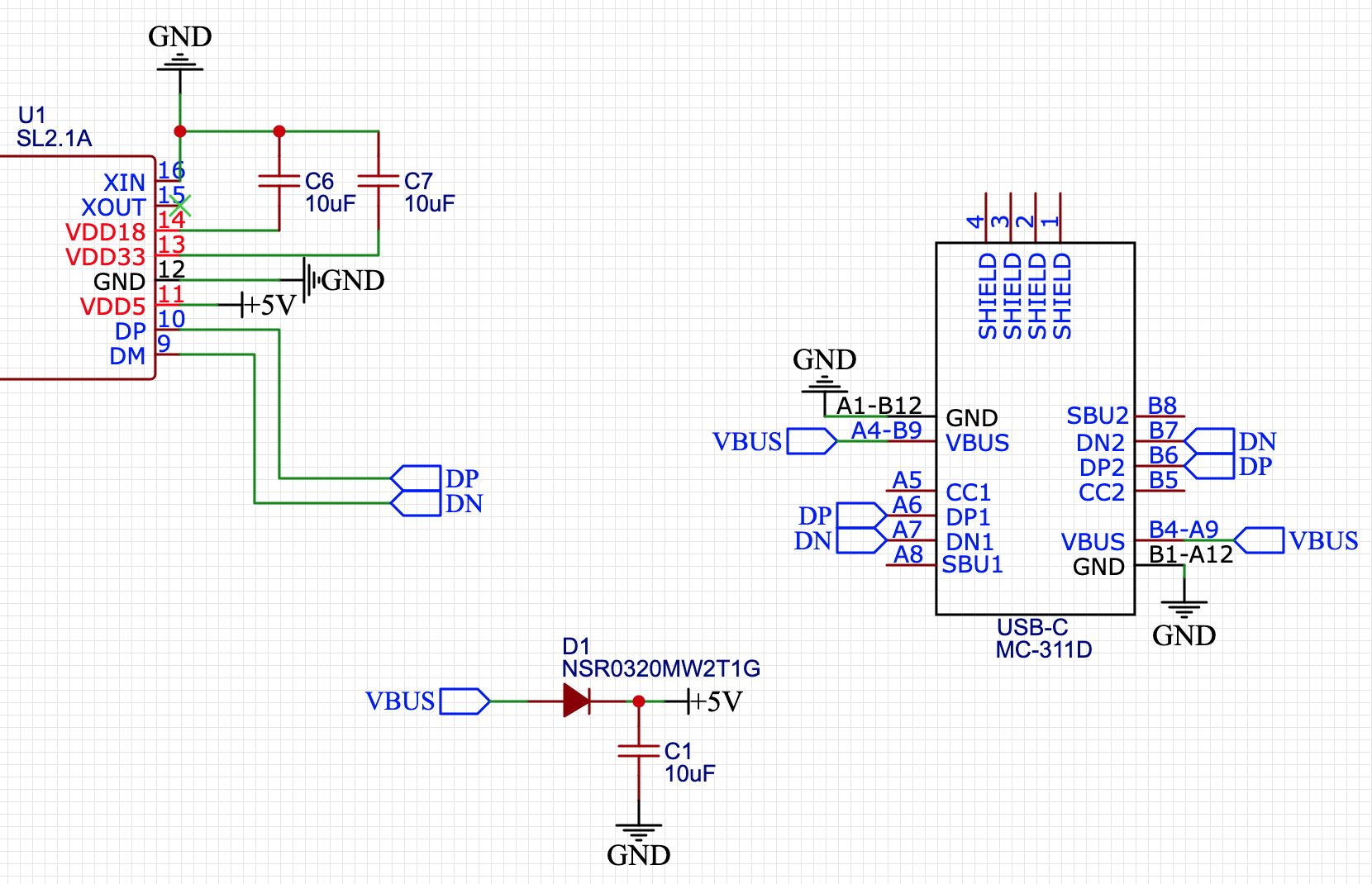
Let's wire up D- again and bring back the diode and capacitor we moved out of the way. If you deleted them, their part numbers are C48192 & C0603.
Rewire the power
Oh, wait! Can't forget that we now have two VBUS pins that should connect to +5V.
This is starting to get a little messy again now that we need to wire up all these parts a second time. Let's clean it up by moving our diode and decoupling capacitor to their own area on the blueprint. Let's use a new net "VBUS" and connect it all together.
The CC pins
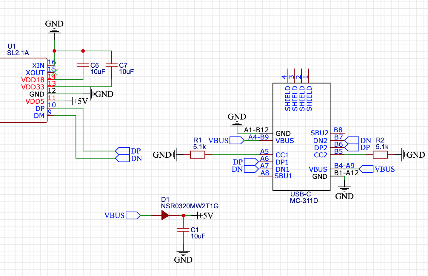
The CC pins are used to negotiate power delivery. The SL2.1A board we're using only handles 5V, so we want to hard-code our board to just ask for 5 Volts.
You can set that value by connecting each CC pin to a 5.1k resistor, then connecting the other end of the resistor to ground.
The SBU pins
SBU stands for "sideband use". It's for cases like Aux audio or Display Port on USB-C. We're not going to use it, so we can just mark it "no connect".

Finishing the schematic
Connect the GND pins to ground, then your schematic is done!
Before we move forward, here's the finished blueprint that you can check yours to:
Build yo' board!
Congratulations! 🎉 🎉 🎉Share your final project with the community